
This Episode I interview Chris of Audio damage. We discuss the new Neuron FM drum synthesis module, where the company comes from and where it is heading. Hope you enjoy!
Tag Archives: mod
How to Mod the Arturia Minibrute and Microbrute! (add LFO out and Waveform Out!)
Modding the Minibrute
For some time now I have really loved the Brute series from Arturia. I also tend to be the type of person to just never be satisfied even when things are going great. So today I decided to modify my brutes. The one feature I always wished the Minibrute had was LFO output so that it could be used to control my modular. Well today I rectified that problem with a simple mod that you can do with very basic tools.
All that is needed is a few mono 1/8″ jacks, some wire, some solder, a soldering iron, a screw driver and a drill.
Here is a list of the solder points and what they are. The video below details not only how to perform this mod, but how to actually find these types of modifications yourself!
Minibrute waveform output list
—- LFO OUTS :
PT34 = SAW LFO , PT32 = TRIANGLE LFO, PT35 = SINE LFO, PT33 SQUARE LFO, PT130 = RANDOM LFO,
PT176 SELECTED LFO
——- VCO OUTS :
PT180 = SQUARE SUB VCO, PT7 = SQUARE VCO, PT119 = TRIANGLE VCO, PT120 = SAW VCO
—————-
MICROBRUTE
TP93= SQUARE VCO, TP94 = SAW VCO, TP102 = SUB VCO, TP124 = TRIANGLE VCO
Korg Kp2 Kaoss pad Pad motion Toggle Mod
Korg Kaoss Pad 2 always lacked one thing
I love the Kaoss pad kp2 but it always lacked a very simple feature. The ability to play your XY modulations without having to touch the unit. Well today I finally got sick of that lack of functionality and decided to do something about it. By installing a simple single throw single pole toggle switch I am now able to trigger my Pad motion without holding down the spring loaded toggle switch. why korg didn’t simply include a button for this is far beyond me but hey, the mod is quite simple and straight forward.
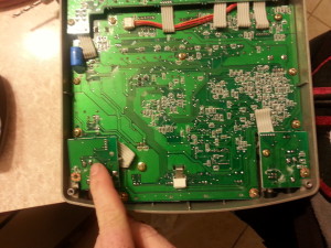
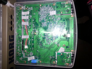
First I took out my multi meter and checked the pins to find where continuity would be breaking and making.
 once you have located the placement of the switch wires to make a path for the switch. remove the microphone input board gently.
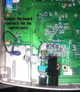
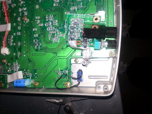 Usiing a Dremel tool make a whole where you want the switch keeping in mind that you need to keep the switch close to the main board so that you don’t hit the capacitors when you reinstall the microphone board.
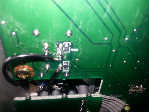 Solder the wiring one leg to each side of the switch. be careful not to over heat the board. If possible bend away any tabs that might come in contact with the microphone board to prevent shorts
 Reinstall the microphone board and put all the screws back in place. you are now ready to have fun !